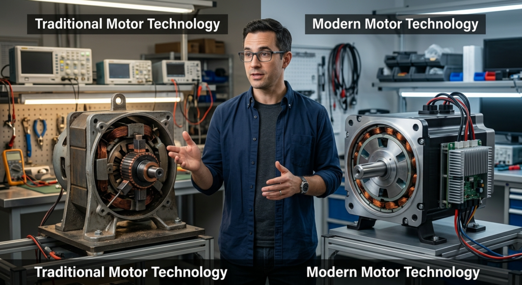
A brushless DC motor, or BLDC motor, uses electronic switching instead of mechanical brushes to keep a permanent-magnet rotor turning. Current flows through stationary stator windings in a controlled sequence, creating a magnetic field that keeps advancing around the motor.
That advancing field is the key. It produces torque on the rotor, while the controller decides which motor phases to energize next and when to switch them.
The simplest mental model is:
DC power → controller → switched stator phases → moving magnetic field → rotor turns
Once that sequence is clear, Hall sensors, sensorless control, six-step commutation, and FOC become much easier to understand.
What Is a Brushless DC Motor?

In the common BLDC design, the rotor carries permanent magnets and the stator contains stationary copper windings. A drive circuit switches current through those windings at the right time to keep the rotor moving.
That is different from a traditional brushed DC motor, where brushes and a mechanical commutator handle the switching. Nidec describes a BLDC motor as using a permanent-magnet rotor, stationary stator coils, and semiconductor switching in place of mechanical contacts.
So “brushless” does not simply mean that somebody removed a wear part. It means the motor uses a fundamentally different way to perform commutation—the process of changing current in the windings so torque continues in the required direction.
What actually replaces the brushes?
Not one component.
The mechanical brush-and-commutator system is effectively replaced by a combination of:
- power semiconductor switches;
- controller logic;
- correctly timed phase switching;
- rotor-position information or estimation when the control method requires it.
This is why a typical bare three-phase BLDC motor cannot simply be connected across two battery terminals and expected to run correctly. It needs drive electronics to create the required phase sequence. Some products hide those electronics inside the motor assembly, so the finished device may still have a simple DC input.
Why is it called a DC motor if its phases keep switching?
Because the drive system normally starts with a DC supply, such as a battery or DC bus.
The controller’s inverter stage then converts that DC power into changing voltages and currents in the motor phases. Nidec notes that BLDC drive circuitry uses an inverter, and also acknowledges that brushless motors can be viewed as AC-driven permanent-magnet synchronous machines depending on the classification convention.
Microchip describes BLDC motors as permanent-magnet synchronous motors commonly associated with six-step trapezoidal control.
For a beginner, there is no need to turn this into an AC-versus-DC naming debate.
The useful answer is:
The battery supplies DC. The controller electronically creates the changing phase currents the motor needs to rotate.
Inside a BLDC Motor: What Rotates and What Stays Still?

Before looking at commutation, it helps to know which parts are doing what.
| PartBasic job | |
|---|---|
| Rotor | Rotates and carries permanent magnetic poles in the BLDC design discussed here |
| Stator | Stays stationary and supports the motor windings |
| Windings | Create magnetic fields when current flows through them |
| Phases | Groups of windings the controller energizes in a controlled sequence |
| Magnetic core | Guides magnetic flux through the motor |
| Shaft/bearings | Support and transmit mechanical rotation |
Renesas illustrates the same basic arrangement: a permanent-magnet rotor surrounded by stationary coils whose current is controlled externally.
Rotor and stator
The rotor is the rotating part.
The stator stays stationary.
In many textbook diagrams, the rotor sits in the center and the stator surrounds it. That is useful for learning, but it is not universal. An outer-rotor motor reverses that physical layout: the magnet-bearing rotor rotates around the stator.
That matters for e-bikes because many hub motors use an outer rotating structure. If you want to compare hub, geared hub, direct-drive, and mid-drive layouts, the site’s motor-type guide covers that separately. Electric Bike Motor Types
The electromagnetic principle is still the same:
stator current creates a field → rotor magnets respond → torque develops
Windings, phases, and permanent magnets
Most beginner BLDC explanations use a three-phase motor, commonly labelled A-B-C or U-V-W.
Those phase names do not necessarily represent three individual coils. A real motor can have many coils and magnetic poles. The coils are interconnected into electrical phase groups that the controller can drive in a coordinated way.
When current flows through a phase winding, that winding contributes to the stator’s magnetic field.
Changing the phase-current pattern changes the direction of the combined field.
That is what prepares the motor for continuous rotation.
How a Brushless DC Motor Produces Rotation

Energizing the stator does not automatically create continuous spinning.
If the controller produced one fixed magnetic field and left it there, the rotor would tend toward a preferred alignment with that field. To keep producing useful torque, the stator field must keep advancing.
How the stator creates torque
Current flowing through the stator windings creates magnetic flux.
The rotor already has a magnetic field because it carries permanent magnets. The interaction between the stator field and rotor field produces electromagnetic torque.
For a simple mental picture, imagine the stator creating a magnetic target slightly ahead of the rotor. The rotor moves toward that new alignment.
Then, before it settles there, the controller moves the target again.
Renesas explains BLDC rotation in essentially this way: current is switched among the stator phases so that the resultant magnetic flux keeps changing position, and the permanent-magnet rotor follows the moving field.
Why the magnetic field must keep moving
This is the concept that makes the rest of BLDC control click.
A fixed field can pull the rotor toward a position.
An advancing field can keep producing torque.
The controller therefore changes which windings carry current as the rotor moves. Each new current combination shifts the stator field farther around the motor.
The rotor keeps following.
That gives us the core BLDC working cycle:
- The controller knows or estimates the rotor’s position.
- It selects an appropriate motor-phase state.
- Current creates a stator magnetic field.
- The magnetic interaction produces torque and moves the rotor.
- The controller advances the phase state and repeats the cycle.
You can reduce the whole process to:
position → switch → field → torque → movement → new position
Electronic commutation is what keeps that sequence synchronized.
How Electronic Commutation and the BLDC Controller Work Together

Commutation means changing current in the motor windings so useful torque continues as the rotor moves.
A brushed DC motor handles that mechanically.
A BLDC motor handles it electronically.
Its controller uses semiconductor switches—commonly MOSFET-based inverter stages in many low-voltage motor drives—to connect the motor phases to the DC bus in carefully timed patterns.
The controller therefore has two related jobs:
- decide which phase state should be active;
- control how much electrical output the motor receives.
Those are not quite the same problem.
Six-step commutation: the easiest switching pattern to visualize
One common BLDC control method is six-step, or trapezoidal, commutation.
One electrical cycle is divided into six sectors. In a conventional three-phase six-step arrangement, two phases are actively driven during each sector while the remaining phase is not actively driven.
A simplified example is:
| StateCurrent path | |
|---|---|
| 1 | A → B |
| 2 | A → C |
| 3 | B → C |
| 4 | B → A |
| 5 | C → A |
| 6 | C → B |
Then the sequence repeats.
The exact phase order depends on motor wiring, desired rotation direction, and controller implementation. This is a conceptual example, not a universal e-bike wiring sequence.
Why six states?
Because each state creates a different stator-field orientation. Moving through the sequence advances that field around the motor.
Microchip’s current six-step documentation describes six 60-electrical-degree sectors with two phases driven at a time.
How does the controller know when to switch?
Knowing which state comes next is only half the problem.
The controller also needs to know when to advance.
There are several ways to obtain that information. Two especially useful ones to understand are Hall sensing and sensorless back-EMF detection.
Hall-sensored control: the motor tells the controller its position
Hall-effect sensors respond to the rotor’s magnetic field.
In a common Hall-based six-step architecture, three digital Hall signals produce six valid rotor sectors during an electrical cycle. The controller reads that state and selects the corresponding commutation pattern.
The important practical advantage is startup.
Hall feedback can provide usable rotor-position information while the motor is stationary, so the controller does not have to wait for the motor to spin before learning where the rotor is.
A simple way to remember it:
Hall control measures rotor position directly.
Sensorless control: the controller infers position
A motor can also be controlled without physical rotor-position sensors.
One common six-step method observes back electromotive force, or back-EMF, in the temporarily undriven phase.
As the permanent-magnet rotor moves past the windings, it generates voltage in them. By observing that electrical behavior, the controller can infer where the rotor is and time the next commutation event.
There is one important limitation.
Traditional back-EMF sensing depends on rotor movement. At standstill there is no useful rotational back-EMF, and at very low speed the signal is difficult to use reliably. A sensorless controller therefore needs a startup strategy before back-EMF-based commutation can take over.
More advanced sensorless systems can estimate rotor position with mathematical observers and other methods rather than relying only on classic six-step zero-crossing detection.
The distinction to remember is:
Hall sensing measures position. Traditional sensorless back-EMF control infers it from the moving motor’s electrical behavior.
What do the phase and Hall wires do on an e-bike motor?
This is where the theory becomes visible on a real e-bike.
A typical three-phase e-bike BLDC system has motor phase connections between the controller and motor. Those conductors carry the switched motor-drive current.
A Hall-sensored motor also needs connections for its position sensors. These normally include sensor power, ground, and Hall signal paths back to the controller.
Their jobs are different:
Phase connections → motor power
Hall connections → rotor-position feedback
Do not assume that wire colors, pin positions, connector shapes, or harness layouts are universal. Manufacturers can combine phase, Hall, temperature, speed, and other signals differently.
That is why an article explaining BLDC operation should not turn into a universal color-matching guide.
Why can bad commutation make a motor jerk or struggle to start?
Think back to the working cycle:
position → switch → field → torque
If the controller has incorrect position information or energizes an unsuitable phase state, the magnetic field may not advance where the rotor needs it.
The result can include rough starting, jerking, weak torque, or inefficient operation.
But those symptoms do not prove that a Hall sensor has failed. Wiring faults, controller problems, poor connections, incompatible components, and other motor-system issues can create similar behavior.
Troubleshooting should therefore test the system rather than replacing whichever component seems most obvious.
Where PWM, sinusoidal control, and FOC fit
Three ideas are often mixed together:
- Motor construction — rotor, stator, magnets, windings.
- Position detection — Hall sensors, back-EMF, encoders, or estimation.
- Control strategy — six-step, sinusoidal drive, FOC, and related methods.
They are different axes.
A Hall-sensored motor does not automatically mean six-step control.
A sensorless motor does not automatically use only one control method.
And FOC is a control strategy, not a physical motor component.
Six-step control advances the motor through discrete commutation sectors. It is relatively straightforward to implement, but switching between a small number of field orientations can contribute to torque ripple. TI specifically discusses commutation-related torque ripple in six-step BLDC control.
Sinusoidal control commands smoother phase-current waveforms.
Field-oriented control (FOC) goes further by mathematically controlling the magnetic-field relationship and torque-producing current. Microchip’s current documentation supports FOC for BLDC/PMSM systems using both sensored and sensorless position methods.
For a general BLDC explanation, that is enough detail.
FOC equations, Clarke/Park transforms, current-loop tuning, and controller programming belong in a dedicated motor-control guide.
Brushed vs Brushless Motors: What Changes in Practice?

Once you know what replaces the brushes, the practical advantages and trade-offs make more sense.
Start with the engineering change rather than a generic list of benefits.
No brushes means one major wear mechanism disappears
Brushes maintain sliding electrical contact with a rotating commutator.
They wear.
Removing them eliminates that particular wear mechanism along with brush-contact friction, sparking, and some associated electrical noise. Nidec identifies brush wear, friction noise, sparks, and electrical noise among the shortcomings avoided by brushless designs.
That is a real advantage.
It does not mean the complete drive system becomes maintenance-free.
A BLDC-equipped e-bike can still have:
- bearings that wear;
- cables or connectors that fail;
- controller electronics that overheat or fail;
- sensors that develop faults;
- insulation and windings that suffer thermal damage;
- gears or drivetrain components that wear, depending on the motor layout.
The accurate claim is therefore:
Brushless removes brush-related maintenance; it does not remove every possible maintenance or failure point.
Are brushless motors more efficient?
They can be, but “brushless” is not a universal efficiency rating.
Removing brush-contact losses is beneficial, and permanent-magnet/electronic-drive architectures allow sophisticated control. But actual system efficiency still depends on factors such as:
- winding resistance and copper loss;
- magnetic/core losses;
- controller and inverter losses;
- motor speed;
- load and torque;
- temperature;
- motor geometry;
- control strategy.
So a claim such as “all BLDC motors are X% efficient” is not useful unless it refers to a specific motor and operating condition.
The same caution applies to comparisons between two e-bikes. Motor construction, controller tuning, gearing, wheel size, battery voltage, rider load, and operating point can matter more than the word brushless printed on the specification sheet.
Are brushless motors quieter and smoother?
Often, but not automatically.
Removing brushes eliminates brush-contact noise. The remaining motor sound and smoothness depend on electromagnetic design, bearings, mechanical construction, switching frequency, and control strategy.
A basic six-step controller can create commutation torque ripple. Smoother current-control methods can reduce torque ripple and acoustic noise, although real performance still depends on the complete motor-drive design.
So “brushless” does not automatically mean:
- silent;
- maintenance-free;
- maximally efficient;
- compatible with every controller;
- sensorless;
- FOC-controlled.
Those are separate characteristics.
The trade-off: mechanical simplicity requires electronic control
A brushed motor can have very simple drive electronics because the motor’s mechanical commutator handles much of the switching.
A BLDC motor removes those mechanical contacts but depends on an electronic controller.
That creates a trade-off:
less mechanical commutation complexity → more electronic control responsibility
For a rider, that complexity is mostly invisible during normal operation.
For system design and repair, however, motor/controller compatibility, sensor feedback, phase switching, firmware, current limits, and thermal behavior can all matter.
The One BLDC Idea Worth Remembering
A brushless DC motor works because the controller keeps moving the stator’s magnetic field ahead of the permanent-magnet rotor.
The windings create the field.
The rotor follows it.
Electronic commutation keeps moving it.
Hall sensors or sensorless estimation can tell the controller when to advance the field, while the control strategy determines how that current is applied.
If you want to zoom back out from the BLDC itself and see how the battery, controller, motor, wheel, and drivetrain work together on an e-bike, continue with How Does an Electric Bike Motor Work?.
Pingback: What Does an E-Bike Controller Do? Amps, Power & Compatibility - electricscootercar.com
Pingback: E-Bike Sensors: Types, Locations & Troubleshooting Problems - electricscootercar.com
Pingback: SEO title: How Does an E-Bike Motor Work? From Pedaling to Wheel Power** - electricscootercar.com
Comments are closed.